Dendrochronology
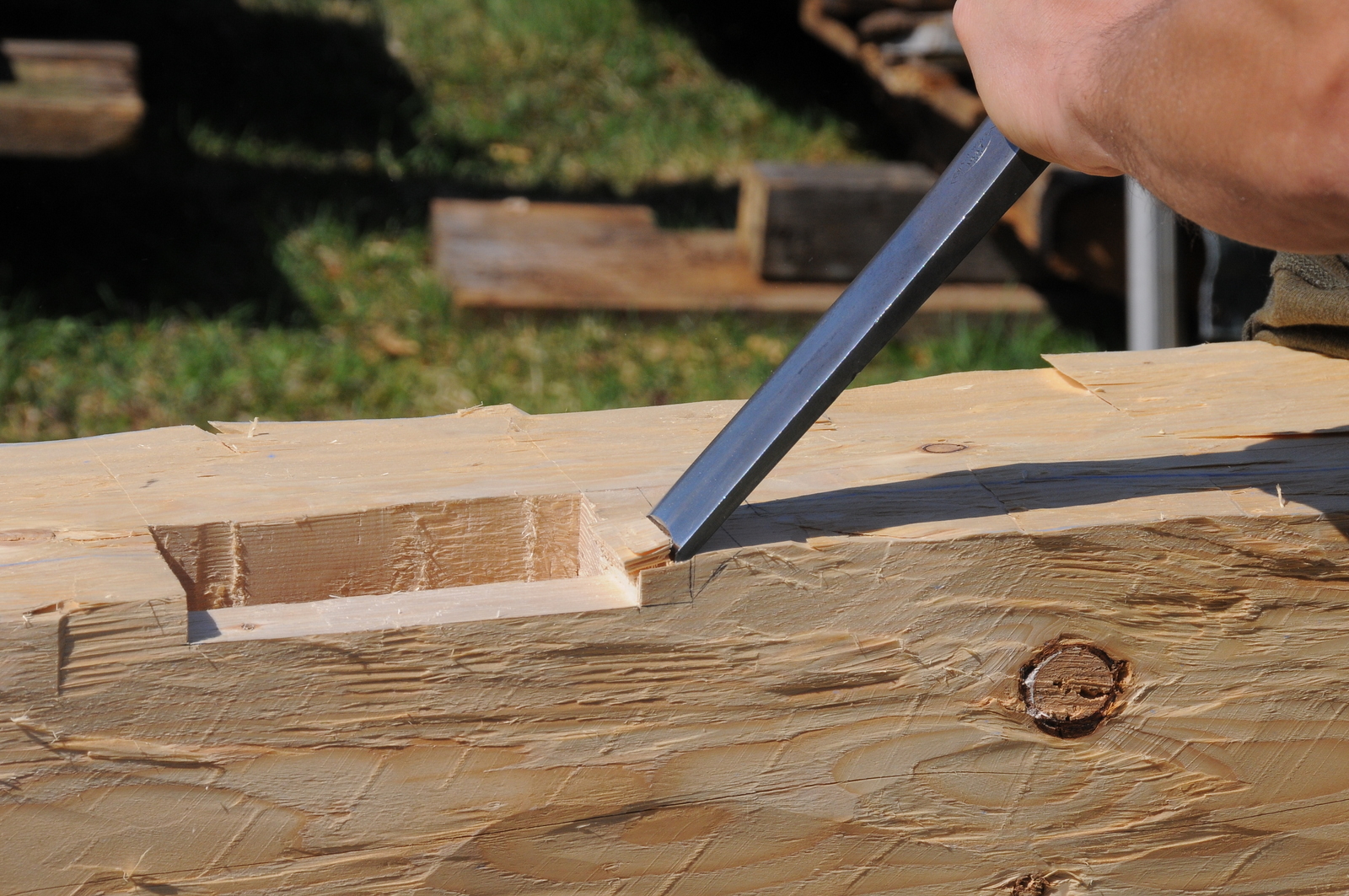
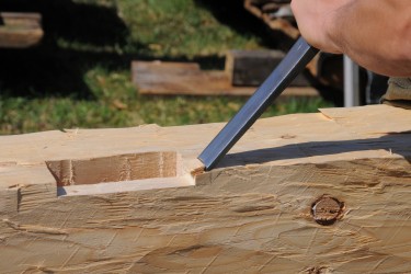
The analysis of timber frames often reveals a great deal about a building’s provenance. The evolution of building techniques, tools and layout methods can offer a great deal of insight about a structure’s origins. Some details, like the marriage marks pictured here, are more obvious than others. The wood itself often contains a more definitive record a building’s age. This can often be revealed through dendrochronology.
Dendrochronology is defined by the Oxford English Dictionary as: “The science or technique of dating events, environmental change, and archaeological artifacts by using the characteristic patterns of annual growth rings in timber and tree trunks.” Using this technology, it is possible to determine the felling dates of timbers used in the construction of timber framed structures with a high degree of accuracy. Typically, early American structures were cut and erected while the wood was still green, often within a year of felling, making dendrochronology a valuable tool in the discovery of construction dates.
Our partner company, Transom Historic Preservation Consulting, provides coring services for the submission of samples to the Oxford Dendrochronology Laboratory located in Oxfordshire U.K. The Oxford Dendrochronology Laboratory works closely with the Research Laboratory for Archaeology and the History of Art at Oxford University and has dated many prominent historic structures throughout the United States. More information about Dr. Daniel Miles, dendrochronology and the laboratory can be found here. For information about rates and eligibility for sampling, please contact me directly.
Dendrochronology
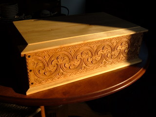
Much like the first time I saw a barn raising, these carved boxes really called to me. I’m a very visual and hands-on type of person and both of these crafts are just that.
The more research I do into the history of early 18th century furniture making the more fascinated I become, particularly with green wood working and solving the mysteries of early layout systems. A compass, square and gouges are the tools used to layout the geometry plus a good eye for aesthetics and spatial patterns.
Most of the original pieces I’ve seen usually have just the front panel carved but I like to carve the side panels as well. When viewing the boxes you can see two faces and with a raking light it is truly stunning.
I use two types of wood for the boxes. I use radially riven red oak for all of the panels and sometimes for the lid. I use sawn eastern white pine as a secondary wood for the bottom board and sometimes for the lid. Oak and pine are used for the interior till compartment as well. The till lid also serves to prop open the main box lid. I enjoy making these boxes entirely with hand tools with the exception of a chain saw to cut the massive oak logs (sometimes twenty four inches in diameter) into smaller sections for riving. From there I use both metal and wooden wedges to open up the log by always riving into halves. I then use a traditional froe to rive the oak into panel planks. Flattening and sizing the boards is achieved with a broad hatchet and hand planes. When the boards have air dried to an acceptable moisture content I begin the carving.
Several years ago, I attended a class at the Yestermorrow deisgn/ build school in Warren VT, on traditional chair making techniques. After working on chairs for a few years I decided to take a class with Peter Follansbee on making traditional 18th century boxes. What began as a source of fascination on the side of my work as a joiner has now grown into an extension of my craft. Please feel free to browse the photos below showing the process of making a box. If you are interested in purchasing any of my pieces or would like something made to order please feel free to contact me at seth@knobbhill.com
Dendrochronology
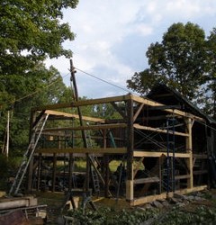
Over the years, we have seen some degree of variation in the motivations and enthusiasm of homeowners in their decisions to restore an historic frame. Granted, anyone who makes the commitment to restore a frame over simply shoring or stabilizing it, tends to have strong sentiments about both the history and the aesthetics of the structure. The owner of this carriage barn in Weathersfield showed the kind of enthusiasm for her barn that rivaled our own passion for what we do. The owner had recently acquired the barn and property of what used to be a part of the farmstead that she grew up on. While we worked on this project, she was there every day to tend her gardens and just sit on the steps and take in the structure. Her love of the barn made this one of the most rewarding and satisfying projects of our career.
The carriage barn was the third such project in a year, of what we saw as being under-built. The structure measured twenty feet wide by forty one feet long but was only composed of three bents. The barn was built in two distinct parts. The original barn measured twenty one feet in length and was composed of two bents. A third bent was added shortly afterward to add another twenty feet to its length. Both structures are built of native softwoods with hewn timbers in the original structure and milled timbers in the addition. The construction of the new section is very similar to that of the original, differing only in that the rafters in the new section are level cut at the plate instead of having step laps. Both sets of rafters are plumb cut at the peaks. The other main difference is that the brace legs in the new section are thirty inches instead of three feet and are made of four by four inch scantlings instead of three by five inch stock. Both the original and the newer sets of braces use inch and a half shoulders and tenons.
The structure has a very simple layout of upper and lower girts of six inch diameter logs surfaced on one face and eight by eight inch timbers for the middle girts. The original structure had sills on three sides as it does now. One oddity was the use of studs along the lower section of the gable wall to the right side of the main doorway. Another thing that struck us as being unusual is that the roof pitch was set to 10 and 7/8 inches of rise per foot of run. We tried all manner of equations and drawings to attempt to find a reason for such an add roof pitch and the general proportions of the frame but could not find any reasonable ratio or design method behind the frames layout.
The tie beams of this frame rest on the post tops with the plates tenoning into the sides of the tie beams at the same height. The original frame used step-lap mortises for the rafters. One innovation that we saw with this frame was that the step-laps on the tie beams for the gable rafters included a two inch level cut shoulder toward the outer reference face that served to prevent lateral movement of the rafters.
The damage to this frame was quite severe. The roof was in poor condition and water had been infiltrating for many years. The two original rafter plates and one of the tie beams were completely destroyed along with two original posts, most of the original girts, floor joists and the sill system. In addition to those timbers that were completely destroyed, there was significant damage to the second original tie beam, one of the plates in the addition and the feet of the two remaining original posts. Essentially, only one of the three bents of the frame was intact.
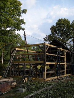
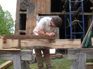
We had contemplated dismantling the entire frame for the restoration, but ultimately chose to remove three quarters of the roof, an entire gable wall and most of the girts between the removed gable and the second bent. The rest of the work was performed in situ. Although we had to replace much of the frame, we were able to recycle many of the damaged parts back into the barn. The damaged gable tie beam was re-cut for use as a replacement post and all of the replacement braces were able to be made from remaining wood from the damaged rafters. We used the opportunity to restore this frame as a resource for hands on demonstrations in conjunction with an historic preservation class held by the Yestermorrow design school in Warren VT. Students were shown how to layout step-lap rafters and develop their skills with traditional hand tools to cut them. Students were also shown how to rive pegs and shape them with a draw knife on a shaving horse.
More often than not, we have to use a crane to lift heavy bents for re-assembly. Every once in a while we find an opportunity where the use of a gin pole is the answer. While we are grateful to the crane operators who assist us in our work, the ability to set up the gin pole and use our own rigging brings a whole other level of satisfaction. The sound of the spinning sheaves as the gable wall was lifted back into place was a great reward and proper finish for a project that involved so little in the way of modern power tools.
This carriage barn is unique in the simplicity of its design. It is an unusual specimen of utilitarian ingenuity that we are truly glad to have been able to preserve. We are especially pleased to have been able to have contributed to the owner’s most thoughtful legacy.
Dendrochronology
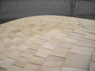
The opportunity to restore this silo was a fascinating deviation from our usual work. We were initially contacted by an insurance company seeking an estimate for the homeowners claim for the collapsed roof. We were glad to oblige with the estimate but assumed that we would not be doing the work as there was no restorative joinery involved. After examining the structure, we found ourselves fascinated at its unique construction along with the challenge of recreating the roof.
Most of the round wooden silos that we have seen are composed of vertical members held tightly in place by the use of metal rings. This silo, however, is composed of rough sawn, two by four inch vertical studs spaced roughly one foot apart. The horizontal sheathing consists of two layers of six inch tall by 1/2″ thick boards on both sides of the studs. Although this feature in itself struck us being unique, our real fascination was with the construction of the roof. The roof was originally constructed as a cone made of tapered staves without any rafters or additional structural support. Each of the two inch thick studs was fastened to the plate, adjacent studs and a two foot diameter wooden disk set a few inches below the peak.
To begin the restoration, we had to remove several layers of the horizontal sheathing from the top and bottom of the silo, mostly on the interior. Much of the sheathing on the top and bottom had rotten or become very brittle. Many of the studs had damage to the ends requiring sisters to be added to about a third of the studs at the bottom of the silo. The tops of the studs had been badly damaged when the plate sections had been torn away during the collapse. We added sisters to all of the stud tops in order to have adequate material to fasten the new plates to.
We fabricated new custom curved sections of two inch thick stock to re-create the original plate. The fabrication of the new roof staves required us to build a sliding jig with almost thirty feet of track to ensure uniformity while ripping the new staves. The new roof is comprised of almost one hundred forty staves that taper from roughly seven inches at the eaves to a quarter of an inch at the peak. A lot of the fun that we had from this project was in the calculating the position of the wooden disk at the top. The height of the disk determines the pitch of the roof as we set the staves. Through examination of the nail holes on the old staves and corroboration with a few old pictures of the silo before the collapse, we were able to locate the disk at the correct height and position. As the body of the silo was rather warped and irregular, any mistakes in the calculation of the disk’s location would not have been immediately self evident nor easily corrected without scrapping materials.
As we began to set the staves, the load of the materials was distributed between the plate and the disk, which rested on a cribbing pile on our staging. In theory, we knew that as the cone began to take shape that the load of the staves would be transferred laterally from each stave to the next and ultimately to the plate with no need for the center disk once the cone was completed. In spite of that knowledge, we couldn’t help but wonder if there would be any settling of the cone once the cribbing was removed from beneath the center disk. Sure enough, when the last stave was set, the cribbing beneath the disk slid out with ease and no movement was detected in the twenty-two foot diameter cone.
The silo proved to be a truly rewarding project for us. We now have a renewed appreciation for the engineering and construction of these fascinating structures and look forward to our next opportunity to save one.
Dendrochronology
This carriage shed was saved in the nick of time. It would not have been likely to survive another harsh Vermont winter. The main problem with this barn was the deterioration of the sill and center post foot on the front eaves wall. The post foot had settled into the soil and rotted so severely that the post was hovering above the ground when we first visited the structure. This problem combined with the settling of the stone foundation and deterioration of the sill and floor system caused deflection and fracturing in the central tie beam and a rafter plate.
The barn is framed with light, softwood timber with a lot of spiral grain and very little in the way of bracing. The small dimensions of the timbers allowed for braces to bend the timbers rather than to remain stiff. Some of the braces had compression failures at the shoulders while others had short tennons that slipped out of their mortises. The end result was that the barn had spread at the post feet and began to lean quite noticeably toward one corner.
The barn has been in the family of the current owner for decades and become a catch-all for generations of objects. When we had first arrived, the barn was so full that we could hardly see the frame to evaluate it. This project brought the whole family together for an amazing feet of sweat equity. The family not only removed and sorted through decades of memories together, but also pulled up the floor boards and removed a collapsed shed from the back of the barn.
Although certain parts of the frame, like the rotten center post and sill system needed replacement, the rest of the frame was able to be pushed and pulled back into place and strengthened. The damage to the rafter plate and center tie beam was such that we were able to support both timbers by using braced lintels and retain the original materials. This frame had a general tendency toward being rubbery due to undersized timbers with three-way connections and several misplaced and unused mortises that left little in the way continuous wood. We added support to the main girt for the second floor and supplemented the bracing throughout the frame without altering any of the original characteristics of the joinery.
When we completed the restoration of the frame and the exterior sheathing the family came back together to lay the new floor and put in repaired window sashes. The barn now houses generations of, now well sorted, family memories once again. We have seen so many of these small barns settling into the ground, held up only by their contents over the years. It was a joy to get to save one.
Dendrochronology
The Gould barn was one of the most challenging and fascinating projects that we have worked on to date. The challenges of the project were largely due to the amount of rot throughout the frame. What was both a greater challenge and an endless source of fascination was the task of deciphering mistakes that had been made during the barns original construction.
The main body of the Gould barn is a classic example of the three bay (mow, drive and stanchion) English barn in its floor plan and proportion. Thirty by forty foot English barns were quite common in Vermont from the earliest era of pre-revolutionary settlement through the late Federal era and beyond. The current incarnation of the barn is configured as a bank barn with the original structure set over an embankment and supported by the addition of a secondary sill system and short posts. The Gould barn had originally been a single story ‘through barn’ with large doors at the eaves walls on both sides of the drive. The barn is ‘square ruled’ with hewn spruce timbers, English tying joints and tapered posts.
The Gould barn features numerous anomalies and mathematical inconsistencies in the joinery layout suggesting that it dates to the period of transition from the ‘scribe rule’ method of layout to the ‘square rule’ method. The earliest timber frame structures were constructed using the ‘scribe rule’ method of joinery layout, whereby each timber and joint is unique and not interchangeable with other timbers in the structure. Using plumb and level as references, each joint was scribed together and marked on its reference face with a chisel, gouge or race knife to identify each timbers unique location in the frame. Scribe ruling gave way to a method known as ‘square ruling’ during the early 1800’s. The square rule relies on mathematical theory for uniform layout, making many of the common parts interchangeable.
The Gould barn utilizes the square rule method but lacks much of the characteristic uniformity associated with the theory behind square ruling. Very few of the braces utilize a common rise or run, making many of them non-interchangeable. The braces at the tie beams have very inconsistent mortise placement, few were identical as you would expect to find with the square rule method. It would seem that the frame of this barn may have been the joiner’s first attempt at using the square rule method. The skill and accuracy with which the joinery was executed indicates that the joiners were by no means novices at their craft.
When we first began to attempt to discover the mysteries of the intent of the original layout of the frame, it had appeared that the builders had been erratic and inconsistent with their lay out. After we began to map the individual parts of the frame it became evident that there was more of regular theme than we had suspected and that the builders had miscalculated the lengths timbers and location of joints rather consistently. One example of this can be found in the layout of the braces that support each of the tie beams. We found the rise and run of many of these braces to be the same but the square ruling at the posts had a high degree of variation. This would make the shoulder lengths and angles vary from brace to brace. Also, with the rise and run not being the same for any given tie beam brace, each brace would have specific laterality so that the brace on the left side of a bent does not fit on the right side even if the shoulder lengths are the same. Unfortunately, not a single tie beam brace was to be found in the barn, only empty mortises. So we are left to speculate as to the specific mistakes that were made in cutting the tie braces.
We suspect that perhaps the builders were under the general impression that all braces of common shoulder lengths were interchangeable. The two pairs of intermediate posts supporting the tie beams at each gable wall had braces with longer runs than rises making the shoulder angles unique from top to bottom. This also means that there is laterality from a brace on one side of the post to the other. Of the eight braces total, only four original braces were in place and all of the same type. If they had cut all eight of the braces identically only four of them would fit, which appears to be the case.
The joinery on the eaves walls was all very uniform and fit snugly. The braces all had legs of equal length and were truly interchangeable. As this is an English tying joint frame, the eaves walls would have been assembled and raised first. Either any kinks or miscalculations (such as a few misplaced mortises) were worked out in the initial assembly of the eaves walls or the uniformity of the joinery gave the builders a false sense of accomplishment with their square ruling endeavors. Almost all of the mistakes were found in the bents and roof system. There were, however, a few remarkable anomalies found in the layout of the eaves walls. The corner posts had reductions to the tops on the outside reference faces creating a slight battering of the outside edge of the post beyond the line between the sill and tie beam. We also observed one intermediate post supporting the plate, mid-span, in the hay mow that featured large, adze swept reductions both above and below all of the girt and brace mortises.
The gable walls had the most noticeable mistakes and anomalies. The upper girts rise over one foot from the eaves posts to the intermediate posts. These girts are cut with shoulders being square to the timbers and having a shoulder length that does not compensate for the additional length due to the rise. An additional complication for many of the girts on the gable walls was that it appears that all of the intermediate posts were cut identically, ignoring the laterality of the referencing schemes. This likely resulted in a panic on raising day when some girts wouldn’t fit and had to be cut down and others were placed having shoulder lengths falling short of the posts.
The worst of the miscalculations were observed in the roof system. The miscalculations could have potentially been catastrophic, but as we have come to see it may have in fact saved the barn. The tie beams seem to have been cut about four inches too short. Our natural assumption is that the builders failed to account for the two inch cantilever of the rafter plates to accommodate the boarding grooves. The stepping of the tie beam ends from the teasel shoulder to the top of the plates seem to have been cut to the right length but the location of the rafter mortises and slope of the tie ends was cut two inches short on each side. This means that the rafter pairs landing on each of the tie beams spanned 30 feet at the height of the plate top instead of thirty foot four. The massive ridge was in actuality only supported by the four pair of tie rafters. The remaining nine pairs of rafters were pegged to the ridge but had a gap of two inches at the birds-mouth at the interior of the plate. With none of these birds-mouth rafters making contact with the plates it would appear that the roof had no real outward thrust and the tie beam rafters, ridge and gable sheathing were enough to prevent the rotten plates from giving way.
From the beginning of the project to the very end, we found ourselves astonished that the frame was able to survive for so long. Although we had to modify the roof so that the rafters made better contact with the plates, we did our best to preserve all of the nuances of the barns original construction.
We identified the property on the 1873 F.W. Beers map and the 1858 H.F Walling map as belonging to “J. Gould.” John Milton Gould was listed as a farmer with 12 cows and 800 sugar trees in the Washington county gazetteer 1783-1889. John lived on the farm with his mother Polly. Polly was married to David Gould in Montpelier on July 5th 1807. David had left the farm to Polly when he died in 1861. John, who never married, lived and worked on the farm with his mother until his death in 1883. After John’s death, Polly moved in with a grandson-in-law in Montpelier where she died in 1884. According to accounts recorded in the Washington county probate records, John and Polly went through some hard times after the death of David. The probate record shows that John and Polly had mortgaged the property more than once after David’s death. The record suggested that both John and Polly were partial to the “intoxicants of alcohol.” John, in particular, was characterized to be lax in his duties on the farm to the point of not fully haying the fields. Polly’s ‘right mind’ and ability to understand her own decisions during the last ten or so years before her death was questioned by the court.
On August 22nd 1873, the farm had been mortgaged to Dennison Taft for a note of $790.00. The debt was incurred for ‘improvement of the buildings’. By 1875 the farm had been foreclosed on first by William N Peck and then by Avery Cummings. Avery’s brother, Henry, acquired Peck’s holding through a quit claim on May 3rd 1877. Although there is no written record of the agreement between Polly and Avery Cummings, it was clear that they had some arrangement whereby Polly and John were able to continue to live and work at the farm. After Polly’s death, Avery Cummings sold the farm at a ‘forced auction’ for a sum of $2,550.00.
All of these factors combined, suggest that the barn dates to sometime between 1805-1815. Knowing that Polly and David had been married in 1807 may mean that this barn had been constructed for them around the time of their marriage. The basement level now beneath the main body of the barn is clearly a later addition featuring well executed square ruling and circular sawn timbers. Several of the hewn post timbers in the basement level appear to be recycled, perhaps from the original sill system. Repairs to the sill system and post feet of the main body of the barn likely occurred at that time. It is entirely conceivable that the repairs to the barn and the addition of the basement level were a part of the ‘improvement of the buildings’ for which money was borrowed in 1873.
There are certain aspects of our trade that become so familiar that it is easy to take them for granted. The odd details of this barn along with its rich history really gave us new directions in our contemplation. The Gould barn has raised our precedent for discovery, and we are grateful for it.
Dendrochronology
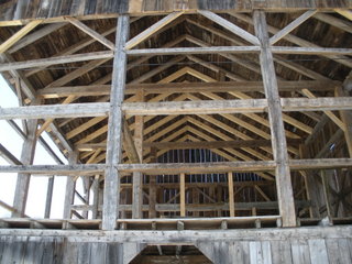
What began with a phone call from a fellow contractor seeking advice about a broken tie beam, turned into one of our favorite restoration projects to date. As it turned out, in addition to the broken tie beam, there was significant damage to both of the rafter plates, a second tie beam, the sill system, post feet and foundation. Although the level of damage to the barn was not uncommon, the barn itself is a rarity.
This barn has everything that we love to see. It is a scribe rule frame with stunning marriage marks, built predominantly of beech and chestnut. It is a classic English threshing barn with tapered posts and English tying joints. The timbers are all hewn with the exception of the scantlings and two sash sawn chestnut posts. Although the technique of scribing timbers continued well into the 1800’s, the abundance of hand wrought nails and the gouge marks around the peg holes (indicating the use of a nose auger), suggest that the barn was likely built in the late 1700’s. Records show that the first saw mill in the town was set up in 1785, leading us to conclude that the barn was constructed within the next twenty or so years.
The current owners of the barn had initially intended to shore the structure so that a cupola might be added. After presenting our research on the history of the barn and property, the current owners became completely invested in completing a full restoration.
When we had first surveyed the barn, we were delighted to see a marriage mark on the interior drive post and tie beam in the shape of a small ‘daisy wheel’. The daisy wheel is a circle, drawn with a compass, that usually contains six, equidistant ‘petals’. Occasionally, circles can be observed with six equidistant marks around the circumference. This type of wheel is referred to as a ‘broken spoke’. The wheel has long been used as a design tool and template for carpenters that allows for complex ratios and proportions to be used in design without carrying out long mathematical computations. Shortly after beginning work on the project, another contractor discovered a daisy wheel of about eight inches in diameter on one of the roof boards, further indicating that the wheel was likely used as a design tool for this frame. Seth was easily able to match the proportions of the frame to the wheel. Although we have seen our share of frames that fit the proportions of the daisy wheel and a number of frames with compass markings, this was the first frame that we have observed with a fully drawn wheel. The roof board with the wheel on it now hangs in the doorway of the barn.
The damage and deterioration of the frame was so wide spread, that we had to fully dismantle it to complete the restoration work. Having the frame dismantled and safely housed in our shop afforded us a great opportunity to restore every aspect of the frame under ideal conditions. We had plenty of space to lay out each wall of the frame for scribing in new material. Although there was a great deal of damage to many of the shoulders, tennons and post feet, we found that once the damaged areas were excavated, the remaining wood was of outstanding quality.
The finish work of the project was carried out by a local contractor after we had set the restored frame on its new foundation. The exterior of the frame was updated sometime during the 1860’s or 1870’s by the Carlton family. The gable and eaves walls visible to the road were covered with clapboards and trim and new sliding doors replaced the original doors that had hung from traditional strap hinges. The homeowners were able to re-use track hardware for the doors. They also opted to omit the addition of clapboards and trim in favor of vertical boarding to show off the details of the visible plate and boarding grooves. They chose shingles for the roof and added beautiful copper gutters which we thought was a really nice touch.
We felt incredibly privileged to work with such dedicated and enthusiastic homeowners to restore this frame that now stands virtually unchanged from its original configuration.
Dendrochronology
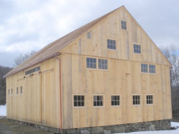
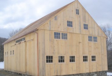
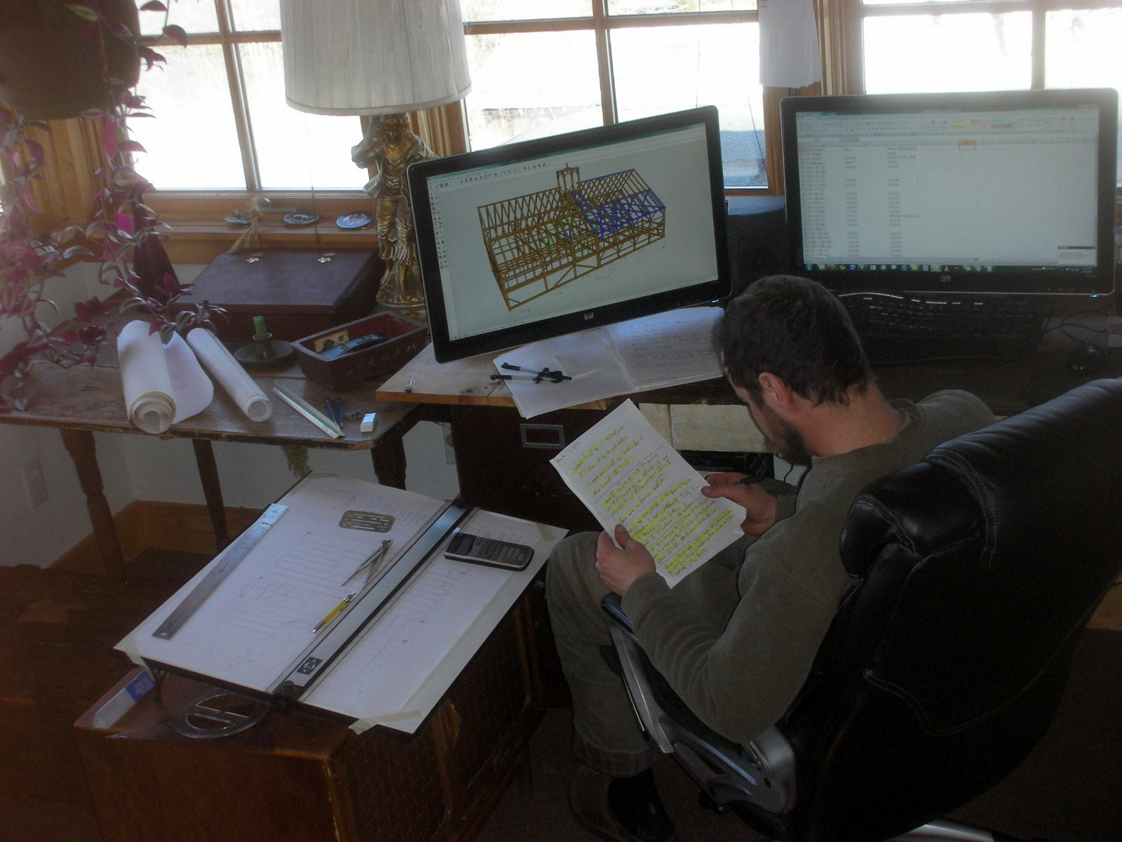
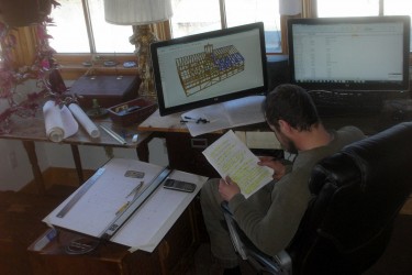
Knobb Hill offers drafting services for purposes of historic documentation in addition to design services for new construction. Our scaled, three dimensional drawings are often used in conjunction with written documentation by those seeking grant assistance. These drawings also serve as blueprints for restoration projects. As with much of our joinery work, we have been accustomed to doing things the ‘old-fashioned’ way. It took a bit of convincing for us to shift our drafting work away from the drawing board and onto the computer. The advantages of the three-dimensional design are undeniable but we still have a soft spot for hand drawing and are glad to do so upon request.
We offer design services for the construction of new residential structures and outbuildings. We have often been called upon to work in collaboration with homeowners to help define goals and uses of space in addition to drafting the joinery and architectural style of the new structure. Although we specialize in pre-Civil War styles of architecture, we are not afraid to bend the rules of specific architectural styles or create entirely unique structures. Our approach to architecture is informed by old traditions of mathematical proportioning. We often draw directly from the five classical orders of architecture as well as the neo-classical interpretations of the orders as found in New England’s historic vernacular architecture. Over the past few years, we have been exploring the almost forgotten art of daisy wheel design and found that many of the earliest structures in Vermont use this simple method to define their proportions. We often use the daisy wheel to define the footprint and basic proportion of new structures and then apply either proportions of the classical orders or to a lesser extent, attributes of the romantic styles of architecture to define fenestration and other embellishments.
Many of the drafts in the gallery below correspond to frames found on the projects page of this site.
Dendrochronology
The challenges of timber framing have brought me great satisfaction over the years and a few frustrations too. I have gained a wealth of knowledge from working with old buildings and studying the craftsmanship of early builders. I’m thankful for all of the framers who have shared their knowledge with me and in turn, I feel a strong responsibility to share my knowledge and help to influence others to work with their hands. In addition to restoring and preserving old frames, teaching is a way that I can give back to the craft that means so much to me.
I have been teaching timber framing since early 2000. I have taught full semester courses in addition to three-week intensives at The Institute of Social Ecology. I have been a regular instructor at the Yestermorrow design/Build School in Warren Vermont with my good friend Skip Dewhirst for many years now. I have also served as an instructor for an intensive at Dartmouth College, lectured for the Historic Preservation program at UVM and instructed local high school students through a grant from The History Channel. Aside from teaching through conventional venues, Michael and I have worked with individuals to teach the craft and assist with the logistics of seeing their own projects to completion.
-Seth Kelley
Dendrochronology
Ever since we participated in our first Vermont History Exposition in 2004, we have been hooked on doing live demonstrations, talks and workshops. We have done hands on demonstrations at the Solar Fest in Tinmouth, the Garlic festival in Montpelier and the International Preservation Trades Workshop in Barre. The opportunity for us to participate in these events not only gives us a chance to share some of our skills and knowledge with others, but also meet and learn from other history buffs. We have made great connections with many older Vermonters who have shared their memories and anecdotes with us. Hopefully, our participation in these events has inspired some of the younger generation to take up an interest in local history as well. In addition to the larger venues of expositions and festivals we have also been participating on a smaller, more intimate scale with local historical societies offering lectures and slide shows. Let us know if there is an event that you think might be relevant to us and keep your eyes peeled for us on the front lawn of the Pavilion Building in Montpelier on July 16th 2011 at the Washington County History Fair.